utility trailer wiring diagram Wiring diagram for livestock trailer
Understanding trailer wiring is crucial for safe and legal towing. Whether you're a seasoned hauler or a weekend warrior, having a solid grasp of trailer wiring diagrams will empower you to troubleshoot issues, perform maintenance, and ensure your lights are functioning correctly. This knowledge can prevent accidents and costly fines.
Utility Trailer Wiring Diagram Explained for Beginners

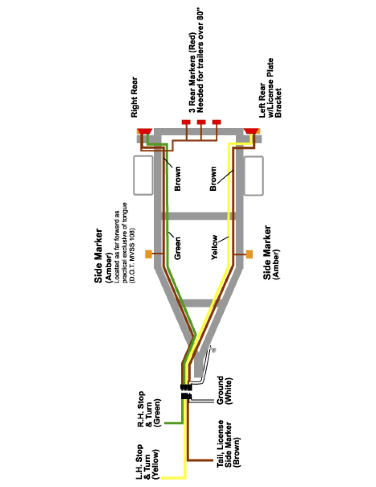
A common starting point for many is the basic utility trailer wiring diagram. This diagram illustrates the fundamental connections required for essential lighting functions. Typically, these diagrams show a 4-way flat connector, which handles ground, tail lights, left turn signal/brake light, and right turn signal/brake light. The color-coding of the wires is fairly standard across the industry, making it easier to identify the purpose of each wire. Brown usually indicates tail lights, yellow is for left turn/brake, green is for right turn/brake, and white provides the ground connection. Following this diagram carefully is paramount to ensuring that your trailer's lights mirror the actions of your tow vehicle, providing clear signals to other drivers on the road.
However, it's important to note that color-coding can sometimes vary depending on the manufacturer or the age of the trailer. Therefore, it's always a good practice to verify the wiring with a multimeter or circuit tester before making any connections. Miswiring can lead to blown fuses, damaged components, or even dangerous situations on the road.
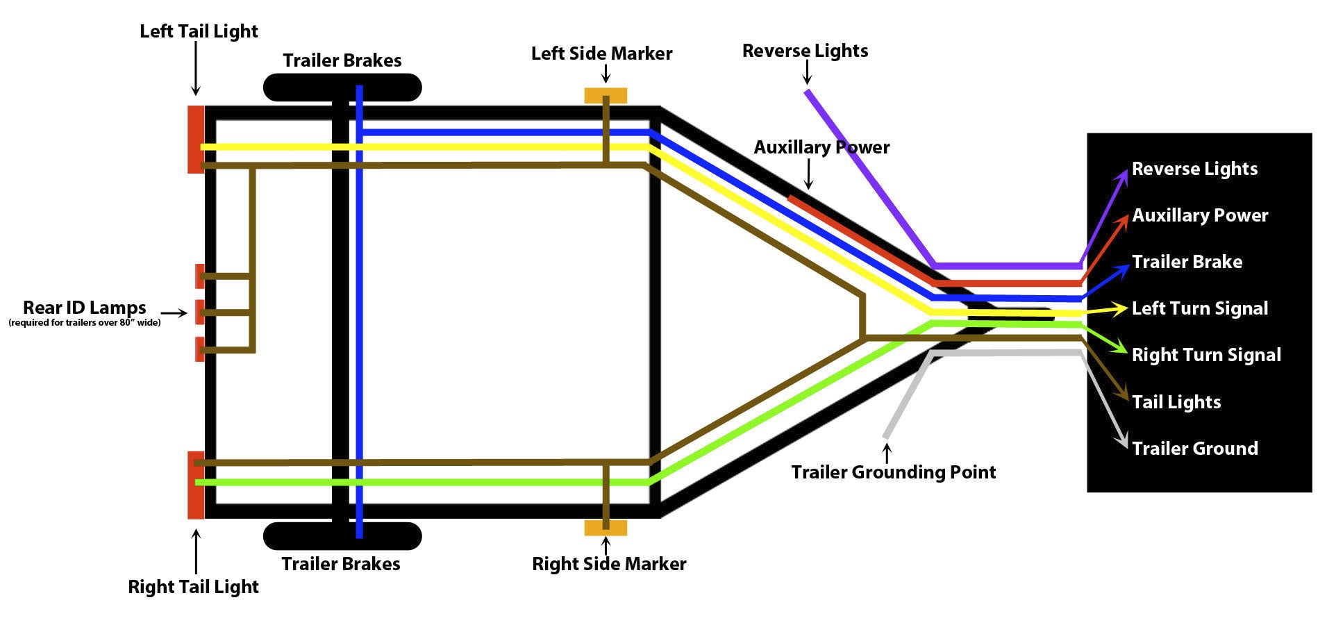
Beyond the basic 4-way connector, some utility trailers may utilize a 5-way flat connector to accommodate hydraulic brakes, or a 7-way RV blade connector which provides additional circuits for features such as reverse lights, electric brakes, and auxiliary power. Understanding the differences between these connectors is critical for selecting the appropriate wiring configuration for your specific trailer and tow vehicle.
Trailer Breakaway Switch Wiring Diagram

For trailers equipped with electric brakes, the breakaway switch is a vital safety component. In the event of a trailer becoming detached from the tow vehicle, the breakaway switch is designed to activate the trailer's brakes, bringing it to a controlled stop and preventing a runaway situation. The breakaway switch wiring diagram illustrates how this switch is integrated into the trailer's electrical system.
The switch itself is typically connected to a small battery dedicated solely to powering the trailer brakes in an emergency. When the breakaway cable, which is attached to the tow vehicle, is pulled from the switch, it completes a circuit, sending power from the battery to the trailer's electric brakes. This triggers the brakes to engage, effectively stopping the trailer.
The wiring diagram for a breakaway switch will typically show the battery connection, the switch connection, and the connection to the trailer's brake wiring. It's essential to ensure that the wiring is properly connected and that the breakaway battery is fully charged to guarantee the system functions correctly in an emergency. Regular inspection of the breakaway switch, wiring, and battery is crucial for maintaining its reliability. Furthermore, it's advisable to test the breakaway switch periodically to confirm that it is functioning as intended. This involves manually pulling the breakaway cable and verifying that the trailer brakes engage. Ignoring the importance of the breakaway switch and its wiring can have severe consequences in the event of a trailer detachment.
If you are searching about Wiring Diagram For Utility Trailer With Electric Brakes - Wiring Draw you've visit to the right place. We have 25 Pics about Wiring Diagram For Utility Trailer With Electric Brakes - Wiring Draw like Utility Trailer Wiring Diagram Explained for Beginners, Utility Trailer Wiring Diagram Explained for Beginners and also Wiring Diagram For Utility Trailer With Electric Brakes - Wiring Draw. Read more:
Wiring Diagram For Utility Trailer With Electric Brakes - Wiring Draw
 www.wiringdraw.com
 Utility Trailer Light Wiring Diagram
 armadau0qmanual.z19.web.core.windows.net
 The Complete Guide To Utility Trailer Wiring Diagram With Brakes
 techschematic.com
 Utility Trailer Wiring Diagram - Cadician's Blog
 2020cadillac.com
 trailer wiring diagram utility 5x8 red plans wing works steel
Trailer Breakaway Switch Wiring Diagram
www.wiringdraw.com Standard Trailer Wiring Schematic
 wireblueprint.com
 Standard Trailer Wiring Schematic
 wireblueprint.com
 Trailer Wiring Diagram Template
 edrawmax.wondershare.com
 Wiring Diagram For Utility Trailer - Wiring Diagram Utility Trailer
 liftmaster-wiring-diagram.blogspot.com
 Step-by-Step Guide: Utility Trailer Wiring Instructions Made Easy
 schempal.com
 Wiring Diagram For Trailer Battery » Wiring Diagram
 www.wiringtrust.com
 Trailer Wiring Diagram 4 Flat: A Comprehensive Guide | AndersGarnow
 www.andersgarnow.com
 Wiring For Utility Trailer Lights
 diagramfixpastures.z4.web.core.windows.net
 Wiring Diagram - Learn How To Design Schematics And Diagram
 wiringdiagram.2bitboer.com
 Utility Trailer Wiring Diagram For Lights
 circuitlibscorned.z13.web.core.windows.net
 Utility Trailer Wiring Diagram With Brakes - Wiring Diagram
 www.diagramelectric.co
 Wiring Diagram For Livestock Trailer
 wiringdiagramall.blogspot.com
 pigtail diagrams truckspring livestock pj boat connectors cimg6 ibsrv plug snowmobile harbor connections circuit loader ez enclosed
Utility Trailer Wiring Harness Diagram
 resolutionsforyou.com
 Utility Trailer Wiring Diagram Explained For Beginners
 schempro.com
 Utility Trailer Wiring Diagram Explained For Beginners
schempro.com Step-by-Step Guide: Utility Trailer Wiring Instructions Made Easy
 schempal.com
 A Comprehensive Guide To Understanding Utility Trailer Wiring Harness
 techschematic.com
 Utility Trailer Wiring Diagram Collection - Wiring Diagram Sample
 faceitsalon.com
 wiring diagram rv power solar keystone motorhome trailer ac system circuit inverter awning georgetown electrical panel breaker heartland camper electric
Trailer+wiring+schematics+and+pictures » Diagram Board
 www.diagramboard.com
 [DIAGRAM] Trailer Wiring Diagrams Information - MYDIAGRAM.ONLINE
![[DIAGRAM] Trailer Wiring Diagrams Information - MYDIAGRAM.ONLINE](https://lh3.googleusercontent.com/blogger_img_proxy/AEn0k_vBZHrK8v-teiRKem9Ym8-WK6UUd-Iyc-fw1sTnxI3l0QOHxbQN61__mqF7401c-EKdm600LDXaTE_mAstial1dPhGqXXgSIFuxgQYtg0wD61ep0IGhO_AliSj0JrXypqyAlEe0qxMeDbZXzjGvk7sKGQgVAYqCnBd54XJ8UK7c-gJIUGDUjW2kHne79WyPbAKrgcC_NUJO01woFQQ=s0-d) mydiagram.online
mydiagram.online Trailer wiring diagram 4 flat: a comprehensive guide. Utility trailer wiring diagram collection. Trailer wiring diagram utility 5x8 red plans wing works steel