Understanding the Amplifier Circuit Diagram: Master the Basics of Audio Design! Best audio amplifier circuit diagram
Alright, let's dive into a couple of amplifier circuits. It's always fun to tinker with these things and see what kind of sound we can get out of them. Understanding the basics of these circuits can really open up a lot of possibilities for DIY audio projects.
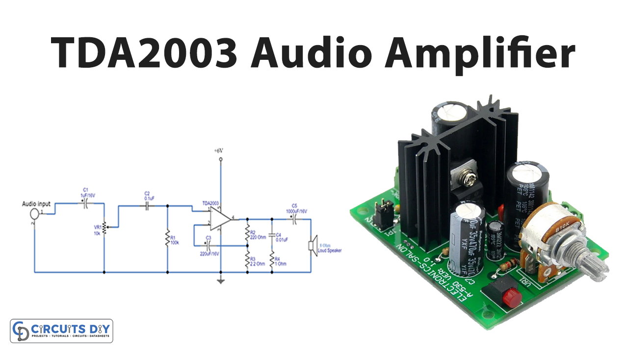
Amplifier Circuit Diagram Using TDA2030
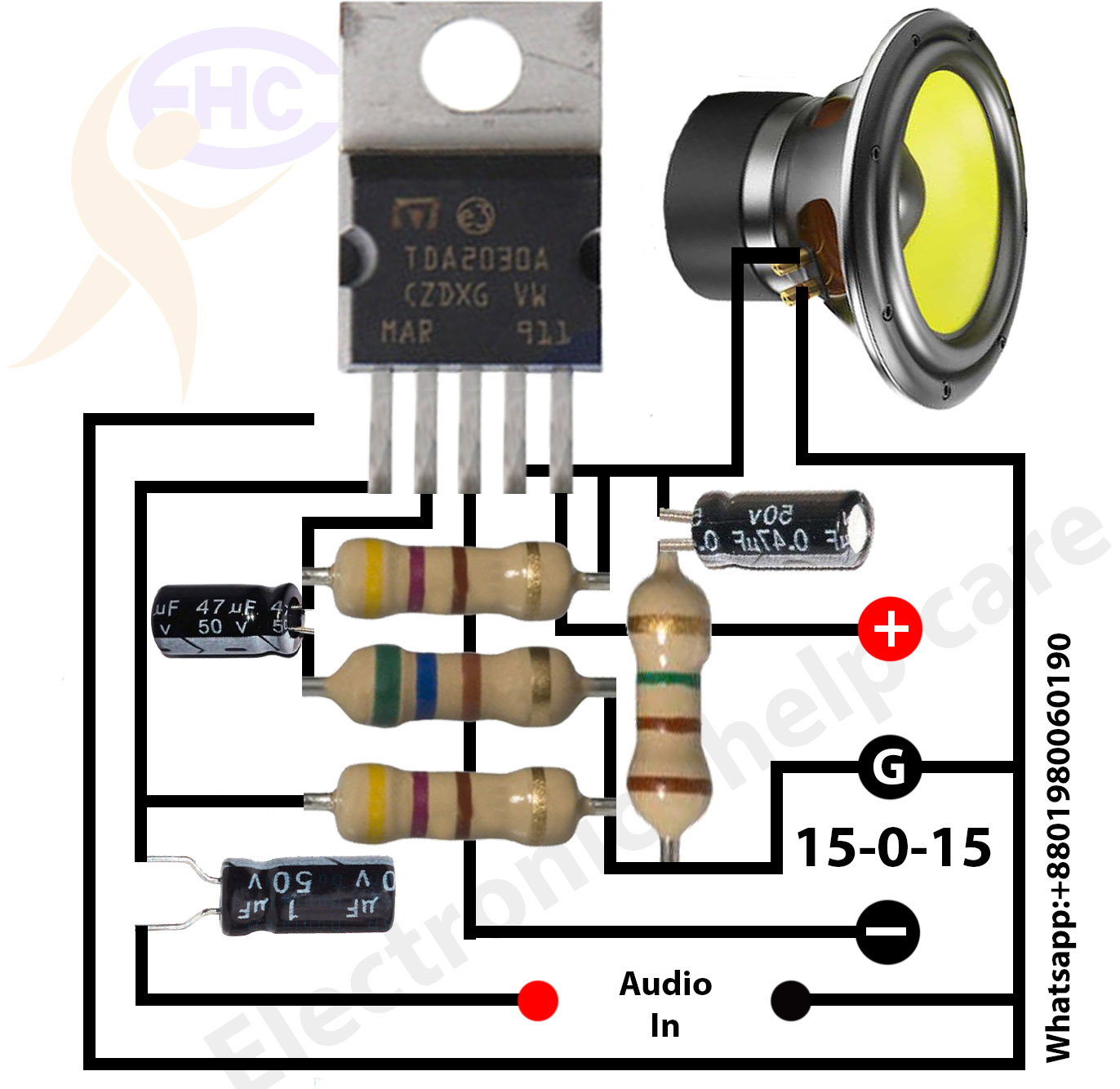
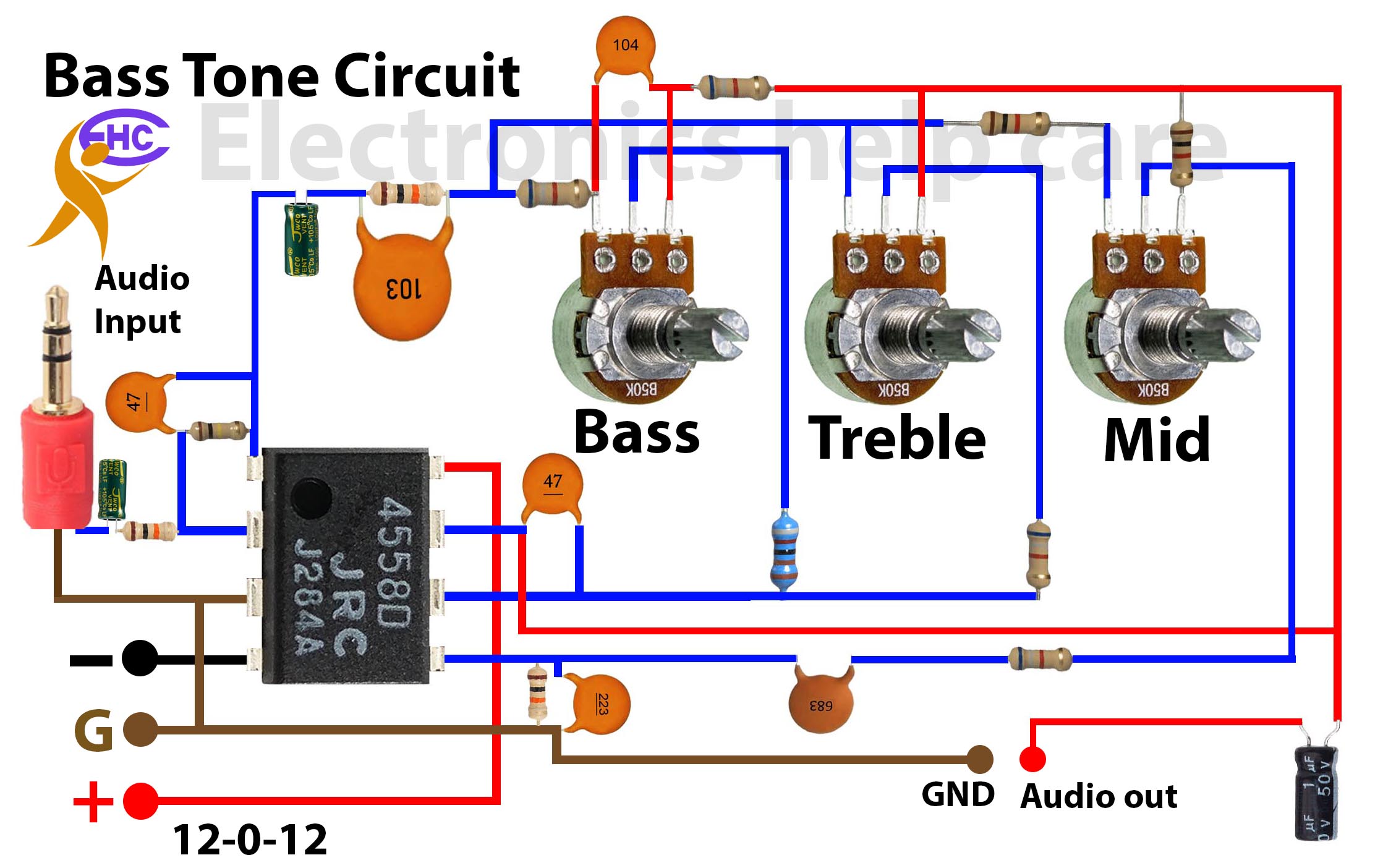
The first circuit we're looking at employs the TDA2030. This is a pretty common IC for audio amplifiers, often used in lower-power applications. The diagram shows the typical arrangement of components required to make this work. You'll notice the power supply connections are crucial, getting the voltage and polarity right is essential – a mistake here can easily fry the IC. The input signal gets fed into the amplifier, and the output is where you connect your speaker. Pay close attention to the feedback network, which typically includes resistors and capacitors. This network controls the gain and frequency response of the amplifier, allowing you to tailor the sound to your liking. Different resistor and capacitor values will alter the sound characteristic. For example, larger capacitors on the input can allow more low frequencies to be amplified, giving you deeper bass. Lower resistor values in the feedback loop will decrease the gain, providing a cleaner but quieter signal. Consider the implications for power supply filtering as well. Clean power is essential to avoid hum and noise in your audio output. Remember to use proper heat sinking. The TDA2030, like most power amplifiers, generates heat when amplifying signals. A heat sink is crucial to dissipate that heat and prevent the IC from overheating and potentially failing. Without it, you might only get a few minutes of operation before thermal shutdown or permanent damage occurs. Experimenting with these parameters is where the real fun begins.
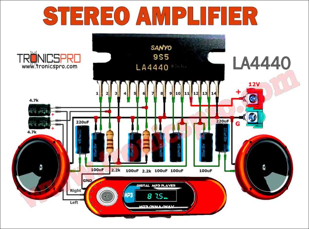
LA4440 Stereo Amplifier Circuit Diagram

This diagram showcases a stereo amplifier using, or similar to the TDA7297, configured in a dual-bridge setup. A dual-bridge configuration allows you to get more power out of the same supply voltage, compared to a standard single-ended amplifier. Essentially, it doubles the voltage swing across the speaker, resulting in a theoretical quadrupling of power. Notice the two independent amplifier channels, each driving its own speaker. This is the core concept of stereo sound, providing a left and right audio channel. The schematic highlights the use of decoupling capacitors on the power rails. These capacitors help to filter out noise and voltage spikes from the power supply, resulting in a cleaner audio signal. Placement of these capacitors is critical; they should be located as close as possible to the IC's power pins. Component selection is also important. Choose resistors and capacitors with appropriate voltage and power ratings to ensure reliable operation. Electrolytic capacitors, for example, have polarity, so make sure to orient them correctly. The diagram highlights the use of relatively few external components. This makes the TDA7297 a good choice for simpler, more compact amplifier designs. The gain for each channel can be adjusted by altering the resistor values in the feedback network. This allows you to balance the volume levels between the left and right channels. Finally, always check the datasheet for the specific IC you are using. The datasheet contains important information about operating voltage, power dissipation, and recommended component values. Ignoring the datasheet can lead to unpredictable results or even damage to the IC.
If you are searching about 12v Transistor Audio Amplifier Circuit Diagram you've visit to the right web. We have 25 Images about 12v Transistor Audio Amplifier Circuit Diagram like Lm741 Audio Amplifier Circuit Diagram, Best Audio Amplifier Circuit Diagram - Wiring Diagram and also Circuit Diagram Amplifier Amplifier Circuit Power 400w Diagram. Here it is:
12v Transistor Audio Amplifier Circuit Diagram
 diagramlistflossiest.z14.web.core.windows.net
 12v Transistor Audio Amplifier Circuit Diagram
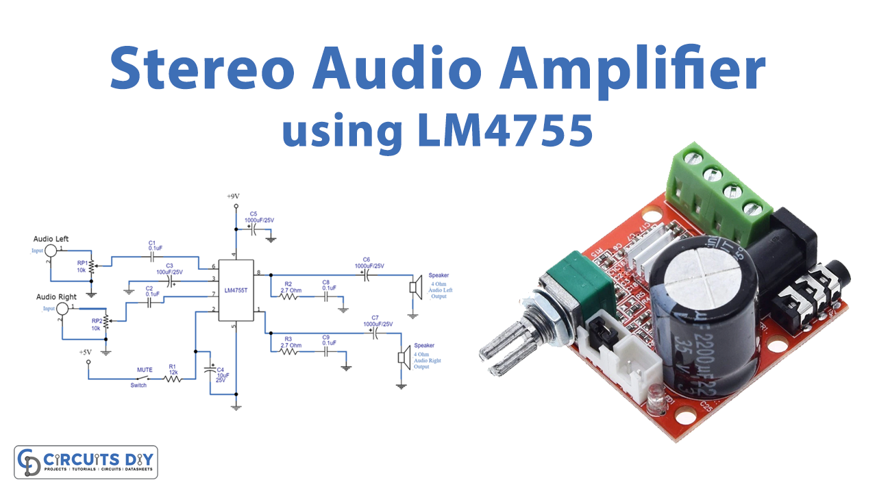
Stereo Audio Power Amplifier Circuit Using LM4755
 www.circuits-diy.com
 Stereo Audio Power Amplifier Circuit using LM4755
Class B Audio Amplifier Schematic Diagram Amplifier Transist
 seebootpzuschematic.z14.web.core.windows.net
 Class B Audio Amplifier Schematic Diagram Amplifier Transist
La 2025 Circuit Diagram America, Your All-new 2025 Toyota La
 terapeftic7circuit.z21.web.core.windows.net
 La 2025 Circuit Diagram America, Your All-new 2025 Toyota La
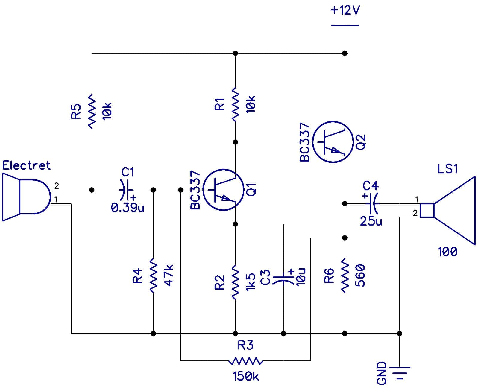
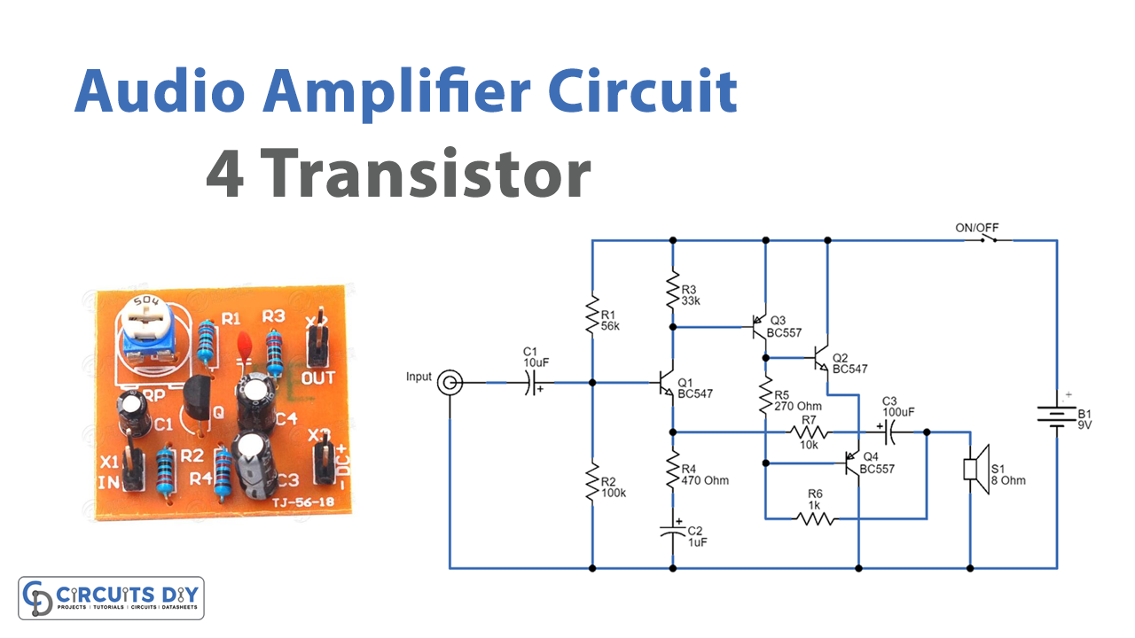
Transistor Audio Amplifier Circuit Diagram 3 Transistors Audio
 ecosdeltorbes.net
 Transistor Audio Amplifier Circuit Diagram 3 Transistors Audio ...
Best Audio Amplifier Circuit Diagram - Wiring Diagram
 www.diagramelectric.co
 Best Audio Amplifier Circuit Diagram - Wiring Diagram
Circuit Diagram Amplifier Amplifier Circuit Power 400w Diagram
 ecircuitdiagrams.blogspot.com
 Circuit Diagram Amplifier Amplifier Circuit Power 400w Diagram ...
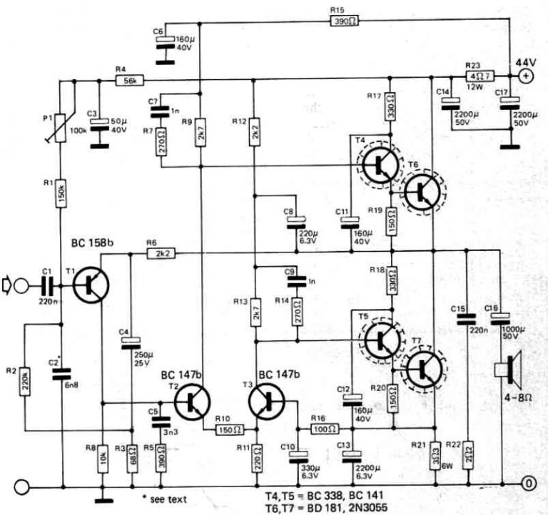
Amplifier Circuit Diagram 2N3055 Transistor 150W - TRONICSpro
 tronicspro.com
 Amplifier Circuit Diagram 2N3055 Transistor 150W - TRONICSpro
BJT Amplifier Design Online Calculator | Ee-diary
 www.ee-diary.com
 BJT Amplifier Design Online Calculator | ee-diary
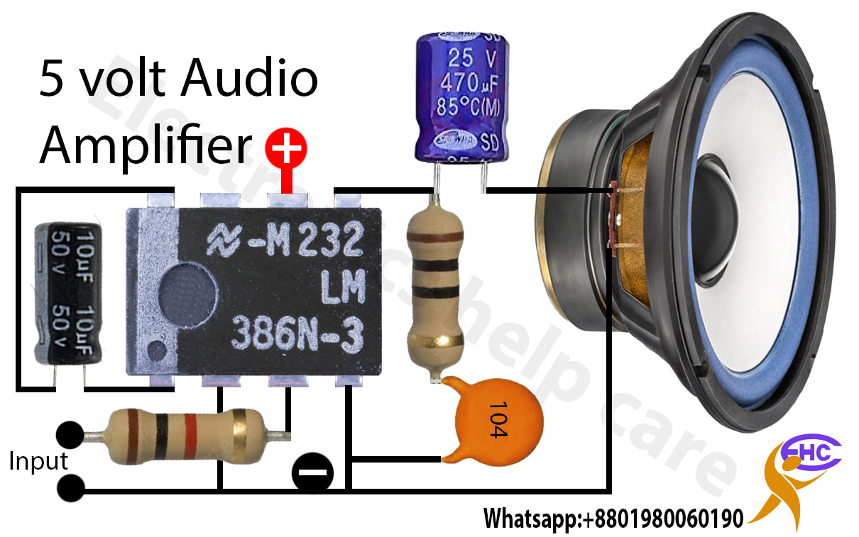
Mini Audio Amplifier Circuit - Electronics Help Care
 electronicshelpcare.net
 mini audio amplifier circuit - Electronics Help Care
What Is Operational Amplifier? Basics Concepts » Hackatronic
 www.hackatronic.com
 What is operational amplifier? basics concepts » Hackatronic
2n3055 Amplifier Circuit Diagram Amplifier Circuit Diagram 2
 jcpaintballamk0libguide.z13.web.core.windows.net
 2n3055 Amplifier Circuit Diagram Amplifier Circuit Diagram 2
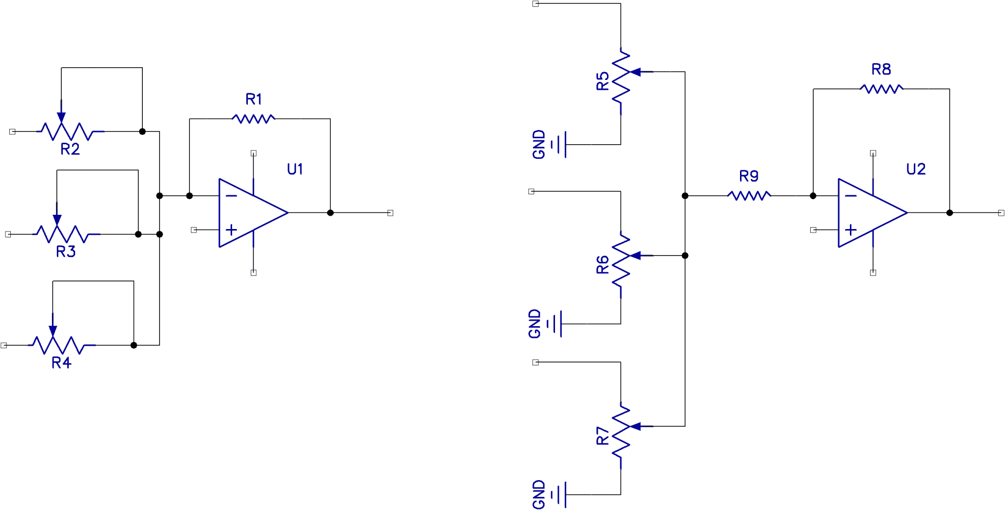
How To Build An Audio Mixer - Circuit Basics
 www.circuitbasics.com
 How to Build an Audio Mixer - Circuit Basics
LA4440 Stereo Amplifier Circuit Diagram - TRONICSpro
tronicspro.com LA4440 Stereo Amplifier Circuit Diagram - TRONICSpro
400W Power Amplifier Circuit Diagram | Audio Amplifier Mini Amplifier
 www.pinterest.cl
 400W Power Amplifier Circuit Diagram | Audio Amplifier Mini Amplifier ...
Transformerless Power Amplifier Circuit Diagram - TRONICSpro
 tronicspro.com
 Transformerless Power Amplifier Circuit Diagram - TRONICSpro
LA4440 Bridge Stereo Amplifier Circuit Diagram Electronics Basics
 www.pinterest.com
 LA4440 Bridge Stereo Amplifier Circuit Diagram Electronics Basics ...
LM380 Audio Power Amplifier Circuits
 www.circuits-diy.com
 LM380 Audio Power Amplifier Circuits
2N3055 Power Amplifier Circuit Diagram - TRONICSpro
 tronicspro.com
 2N3055 Power Amplifier Circuit Diagram - TRONICSpro
Build A High Quality Audio Amplifier With The LM1875 - Circuit Basics
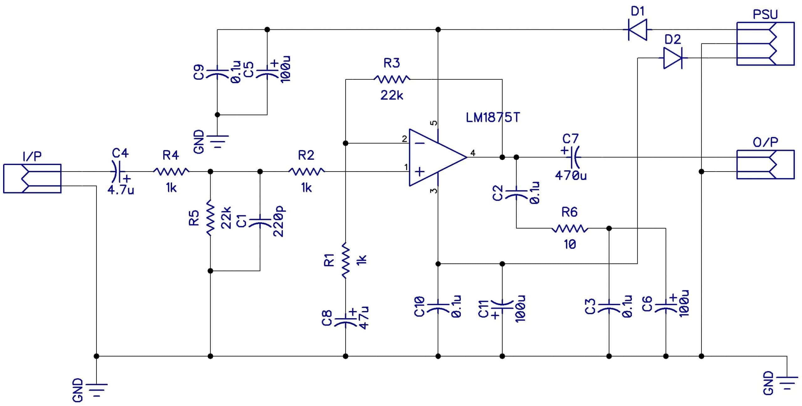 www.circuitbasics.com
 Build a High Quality Audio Amplifier with the LM1875 - Circuit Basics
Circuit Diagram Amplifier Amplifier Circuit Power 400w Diagram
 ecircuitdiagrams.blogspot.com
 Circuit Diagram Amplifier Amplifier Circuit Power 400w Diagram ...
Understanding Amplifier Circuits: A Comprehensive Overview
 hilelectronic.com
 Understanding Amplifier Circuits: A Comprehensive Overview
Lm741 Audio Amplifier Circuit Diagram
 www.circuitdiagram.co
 Lm741 Audio Amplifier Circuit Diagram
Toa Amplifier Circuit Diagram [view 41+] Toa Amplifier Schem
scouts1kzkwire.z14.web.core.windows.net Toa Amplifier Circuit Diagram [view 41+] Toa Amplifier Schem
Inside The Black Box: Understanding Amplifier Feedback
 audiocurious.com
 Inside The Black Box: Understanding Amplifier Feedback
circuit diagram amplifier amplifier circuit power 400w diagram .... 400w power amplifier circuit diagram. Lm380 audio power amplifier circuits